Building it
Start with the PIRs
The Adafruit PIRs come with a one foot cable that can be plugged into the PIR. Alternatively, you can use three female jumper, or just solder directly to the header on the PIR. I used the supplied connector, but cut it down to a few inches. Just long enough for the cable to extend out of the PIR housing, but long enough that the 4-wire phone cable I had purchased could be soldered to it. And then shrink wrapped. Twice. Once on each of the three (four on the bottom PIR) leads, and then again to hold the wires together.
I added the photoresistor to the PIR placed at the bottom of the stairs. There were two reasons for this.
- The wire run between the photoresistor and Trinket M0 was shorter
- It tended to be darker at the bottom of our stairs
The PIR case was modified by drilling two small holes in the side to allow the photoresistor leads to go through.
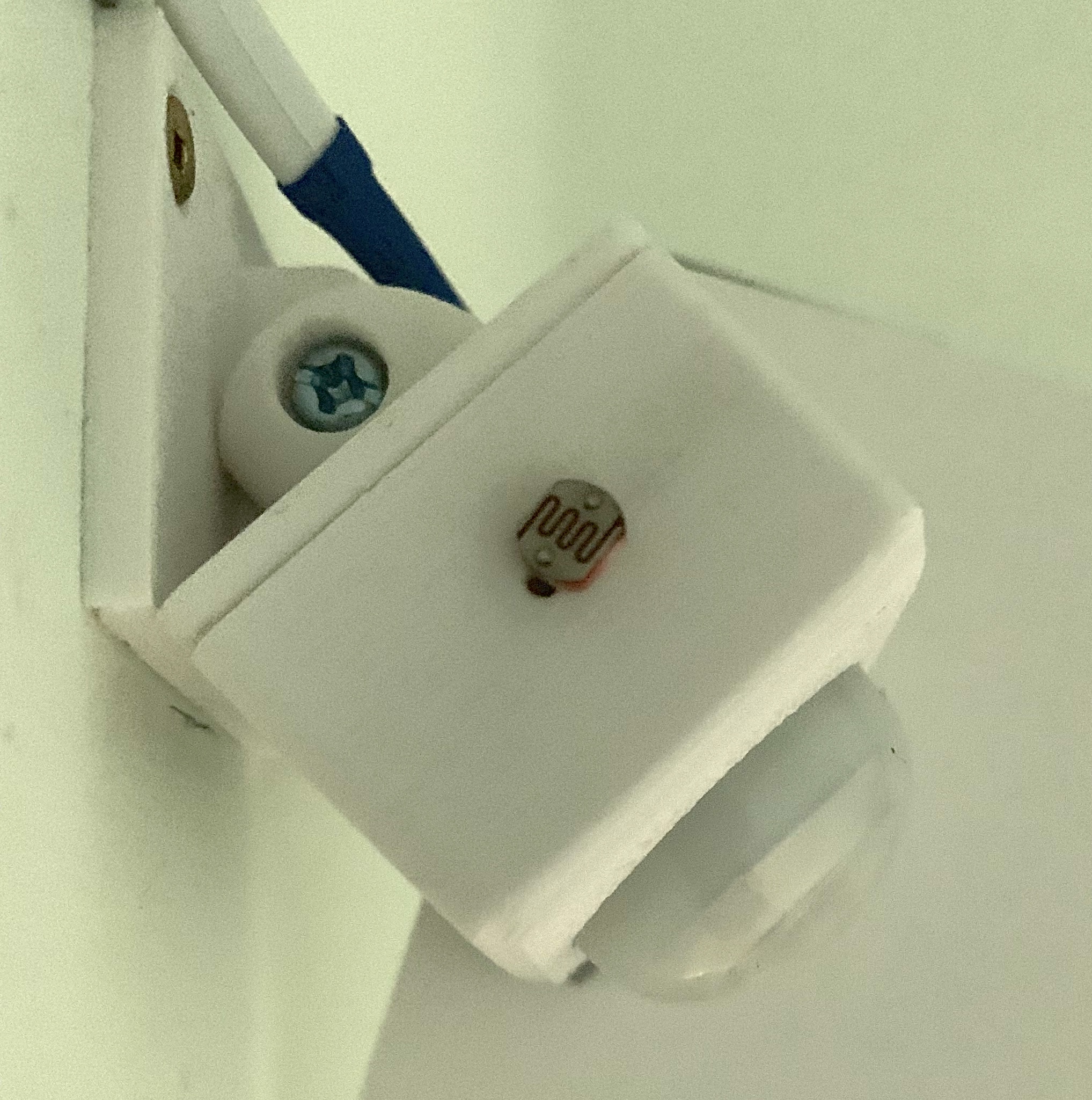
PIR case with photoresistor installed
Inside the case, one lead of the photoresistor is connected to +5V on the PIR. The other lead is attached to the yellow lead in the 4-wire cable running back to the Trinket M0. Shrink wrap tubing was put in place before the photoresistor leads were soldered. The remainder of the voltage divider is implemented inside the case containing the Trinket M0.
The PIR sensor is screwed into the case. You'll be tempted to install the M3x19 screw that holds two of the three parts of the case together. But, it's much easy to screw the base plate to the wall and then install the M3x19 screw and nut.
The PIR red wire is connected to the 4-wire cable red, as are the black leads. Connect the PIR yellow wire to the 4-wire cable green for the PIR output.
The final bit of this part is to decide how much cable you need to reach from the PIR when it is installed back to the Trinket M0 enclosure. I "dry fit" my installation. That is, I used gaffer's tape to "install" the PIR and route the cable back to the Trinket M0. I did this with both PIRs to get good measurement for the cables — basically adhering to the old adage "measure twice, cut once."
The cables from the PIRs to the Trinket enclosure were installed using the double side mounting tape. I was able to hide the cable from the upper PIR in a fold in the molding running beside the stairs. The wire to the bottom PIR was simply taped to the wall using the same double sided tape cut to the same width as the cable. Here's a sample.
Bottom PIR wiring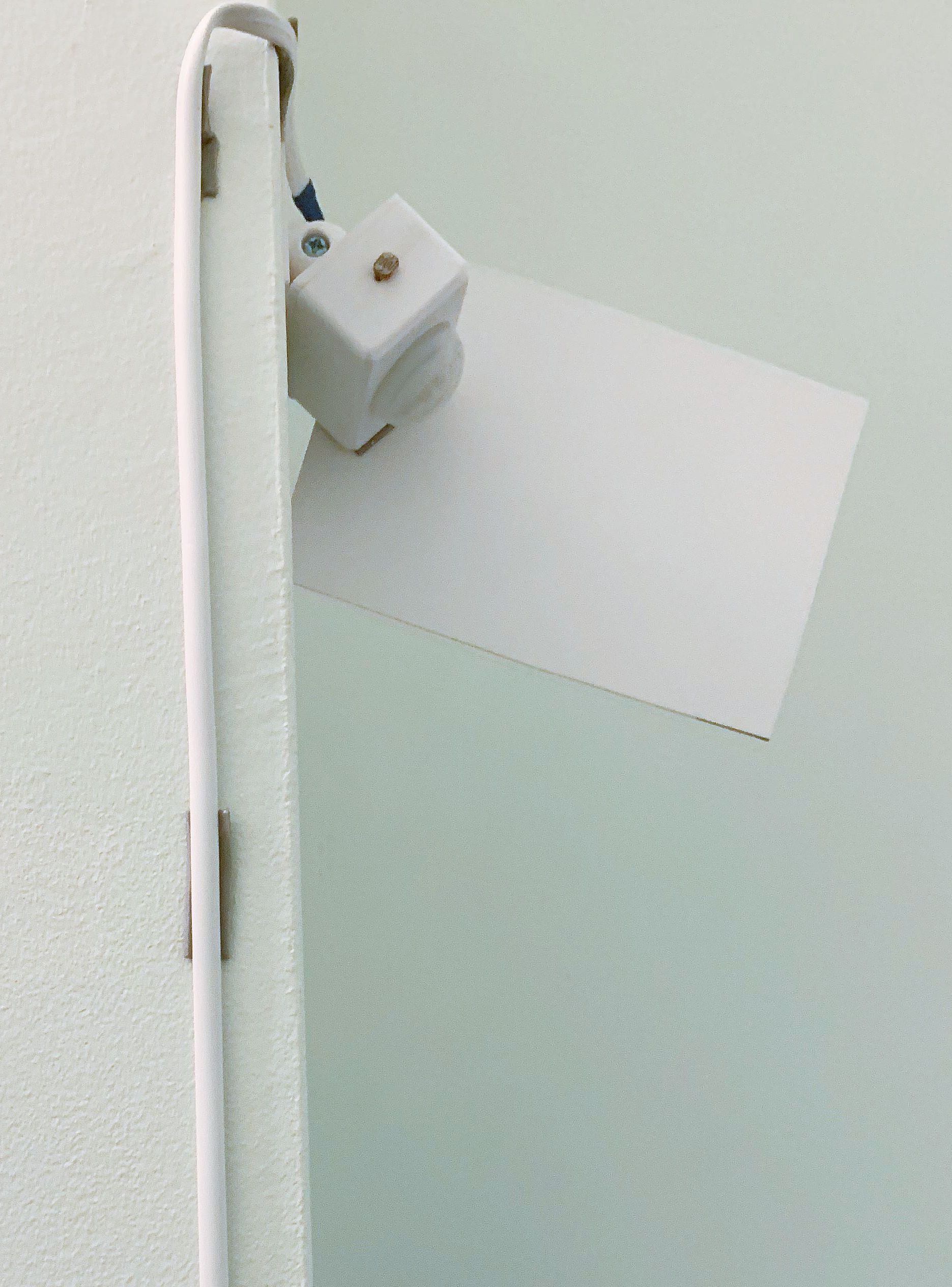
The Trinket M0 enclosure
To mount the barrel connector and switch, I drilled holes in one end of the enclosure.
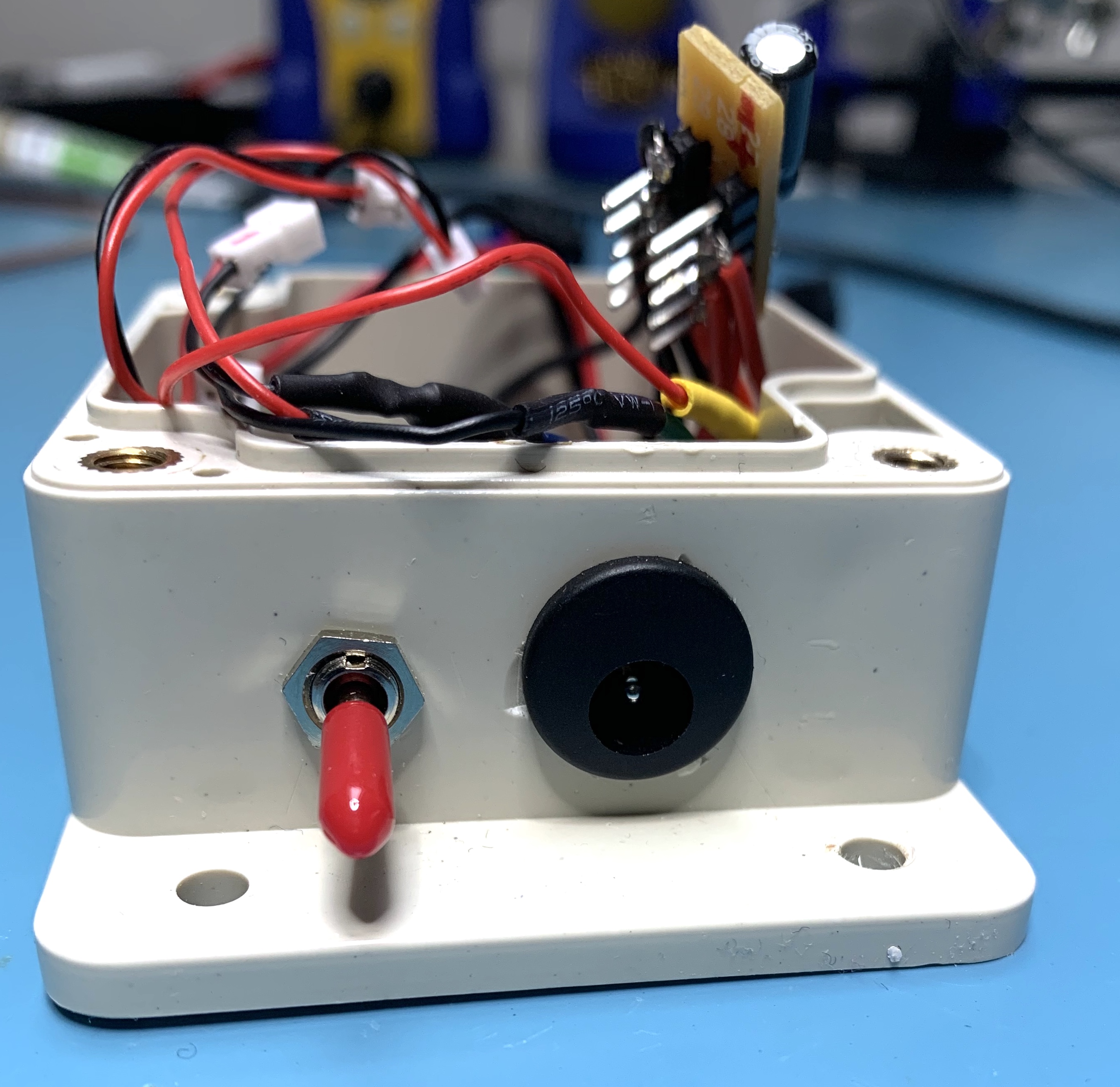
Enclosure, switch, and barrel connector
At the opposite end, I drilled 3 holes large enough for the wiring to exit. One each for- LED power and signal
- Power and signal to the top PIR
- Power, signal and photoresistor to the bottom PIR
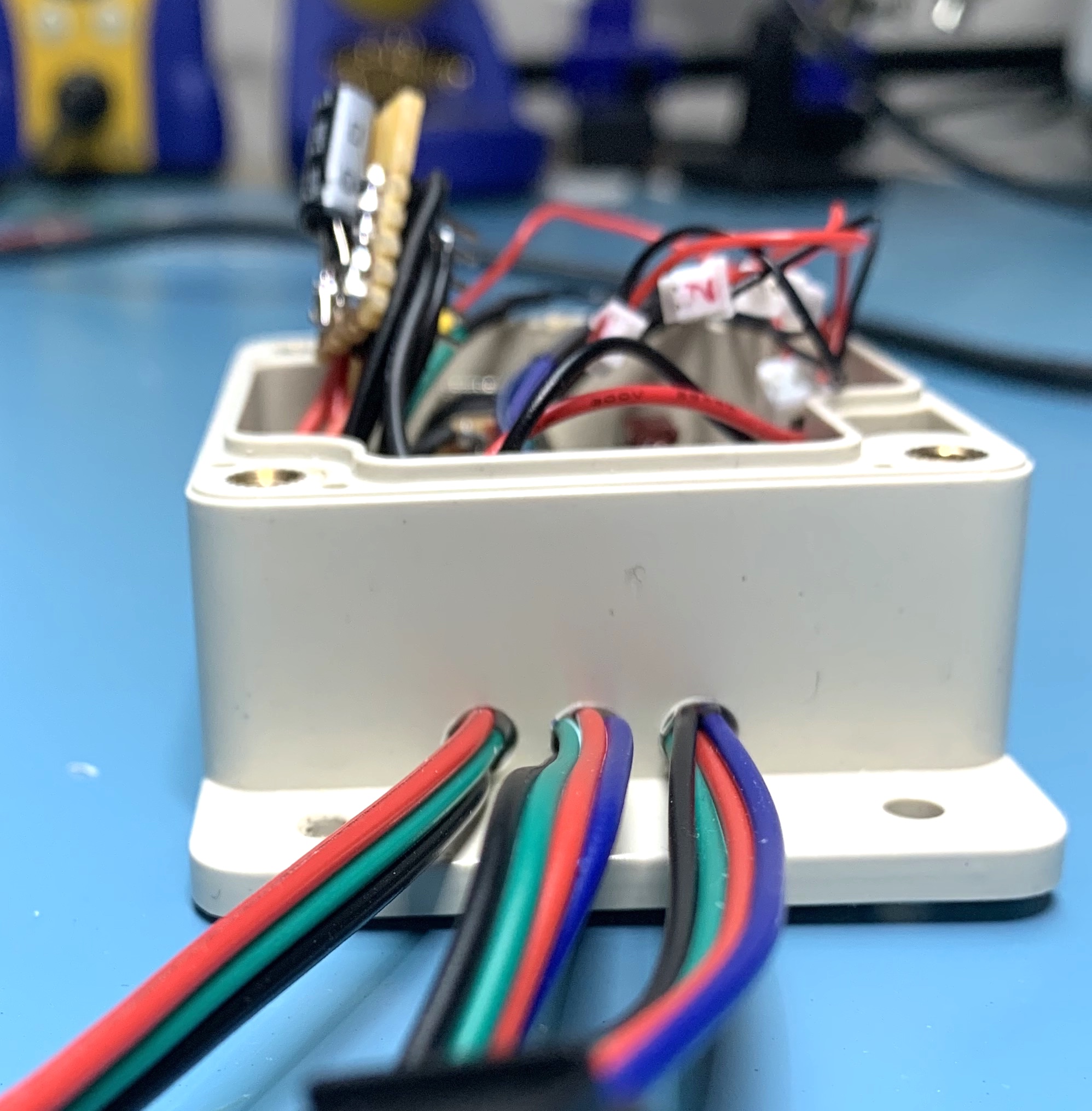
Enclosure, cable exit
To provide strain relief for the 3 cables, I drilled small holes through the bottom of the enclosure to feed small tie-wraps through.
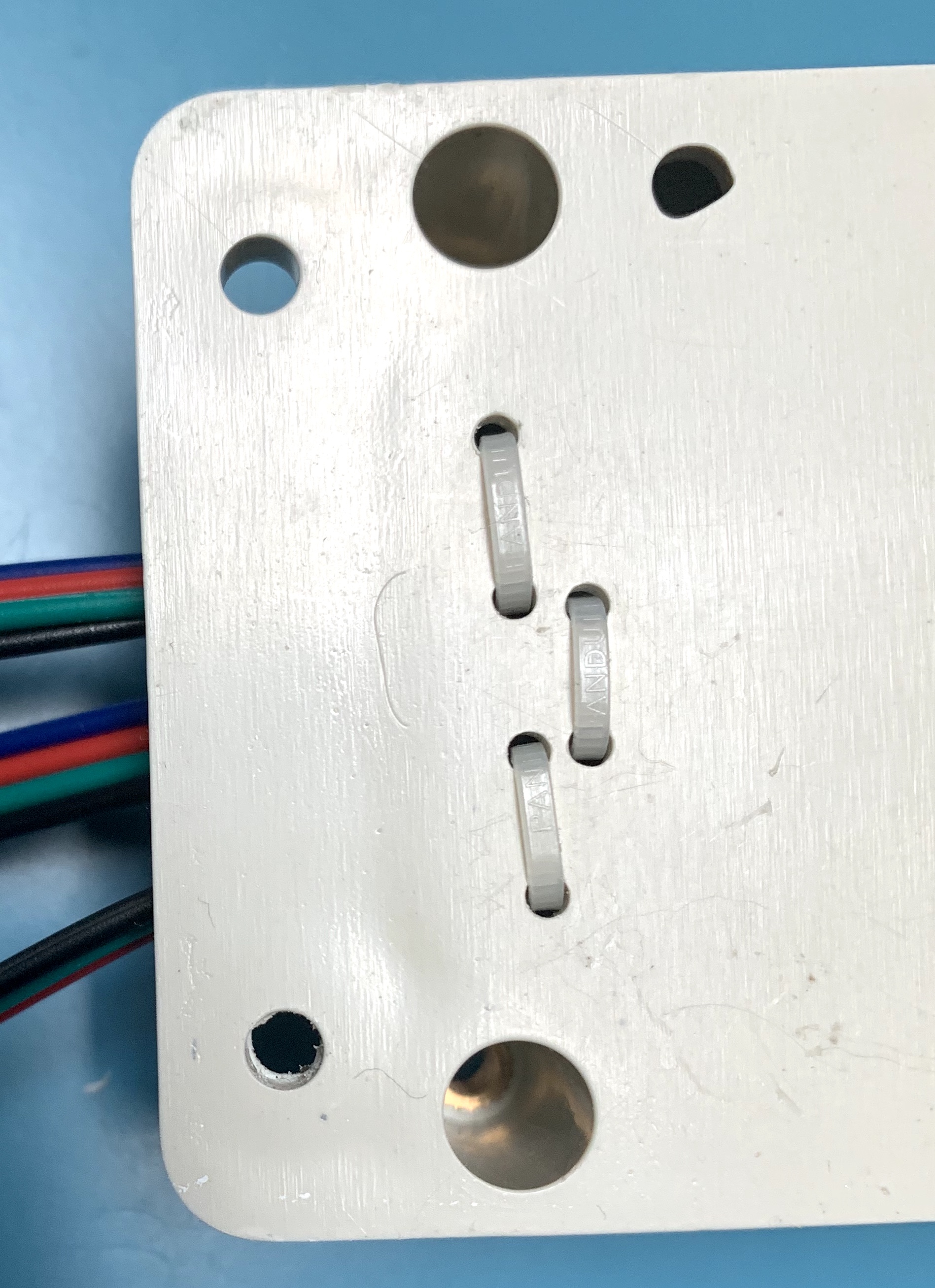
Enclosure cable strain relief
Power and ground
I wired the LED strip power and ground connector directly to the barrel connector. I also wired from the barrel connector to my small power distribution board. From the distribution board, you need connections to
- the JST 2-pin cable with female connector. This will power the Trinket
- the cable going to the upper PIR
- the cable going to the lower PIR
- a ground connection to the 2.2K ohm resistor for the photoresistor voltage divider
The power and ground distribution board was made by soldering 2 five element headers into my perf board. On the under side I solder bridged each row together so that one row of 5 pins could be used as ground, and the other 5 pins as +5V. The 100µf capacitor was also soldered onto the bottom side of the distribution board — being careful with the polarity on the capacitor.
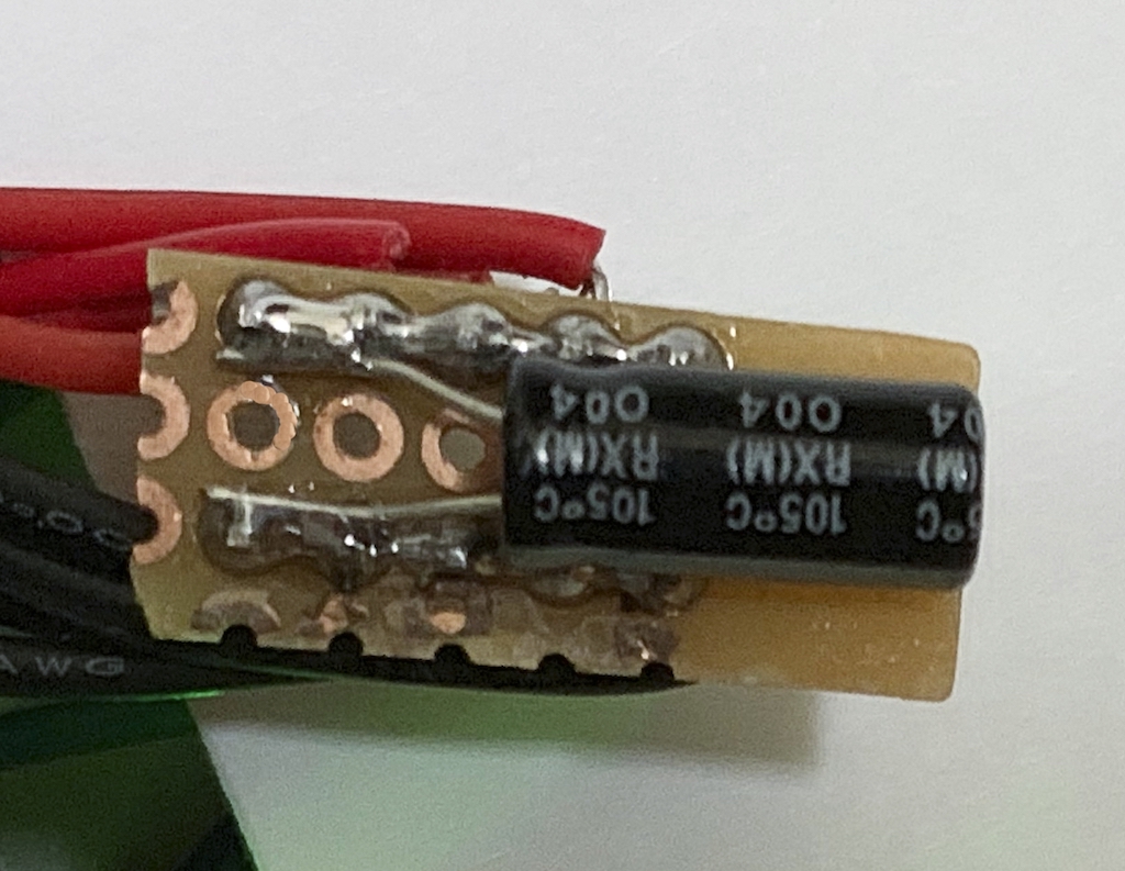
Power distribution board, solder side
I wired the switch to one of the micro JST connectors for ease of connecting/disconnecting to the Trinket M0.
Here's a rough as-built Fritzing diagram. I wasn't able to find and didn't have the patience to create graphics for the micro JSTs. Or for that matter, the male and female sides of the JST connectors. So in this diagram the same connector is used for both sides of the connector. Klunky, but provides a representation of how the project was put together.
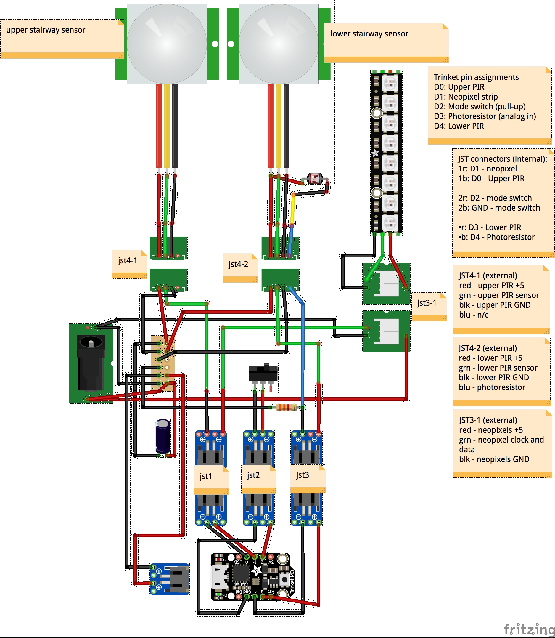
Fritzing, as built
To keep things straight, I wrote numbers on the micro JST connectors so I wouldn't plug things together incorrectly. I went one step further by swapping one of the JST connectors (the one labeled 2 in this case) to have the male side soldered to the Trinket M0. I also alternated the male/female ends of the connectors for the top and bottom PIRs. That way it was impossible to plug in the wrong PIR and have things work oddly.
The wired up Trinket M0 looks like this
Wired Trinket M0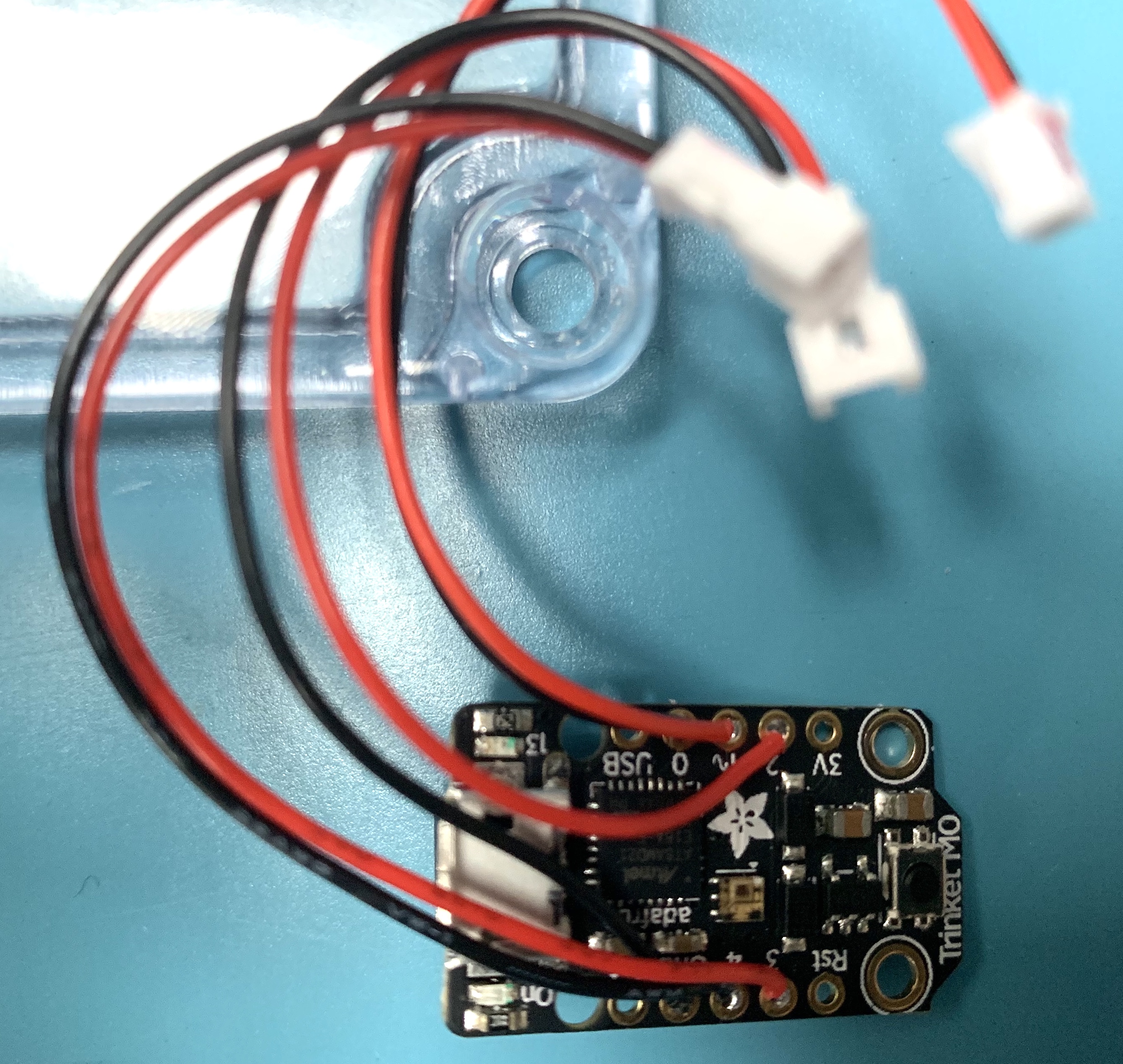
And the resulting wired enclosure
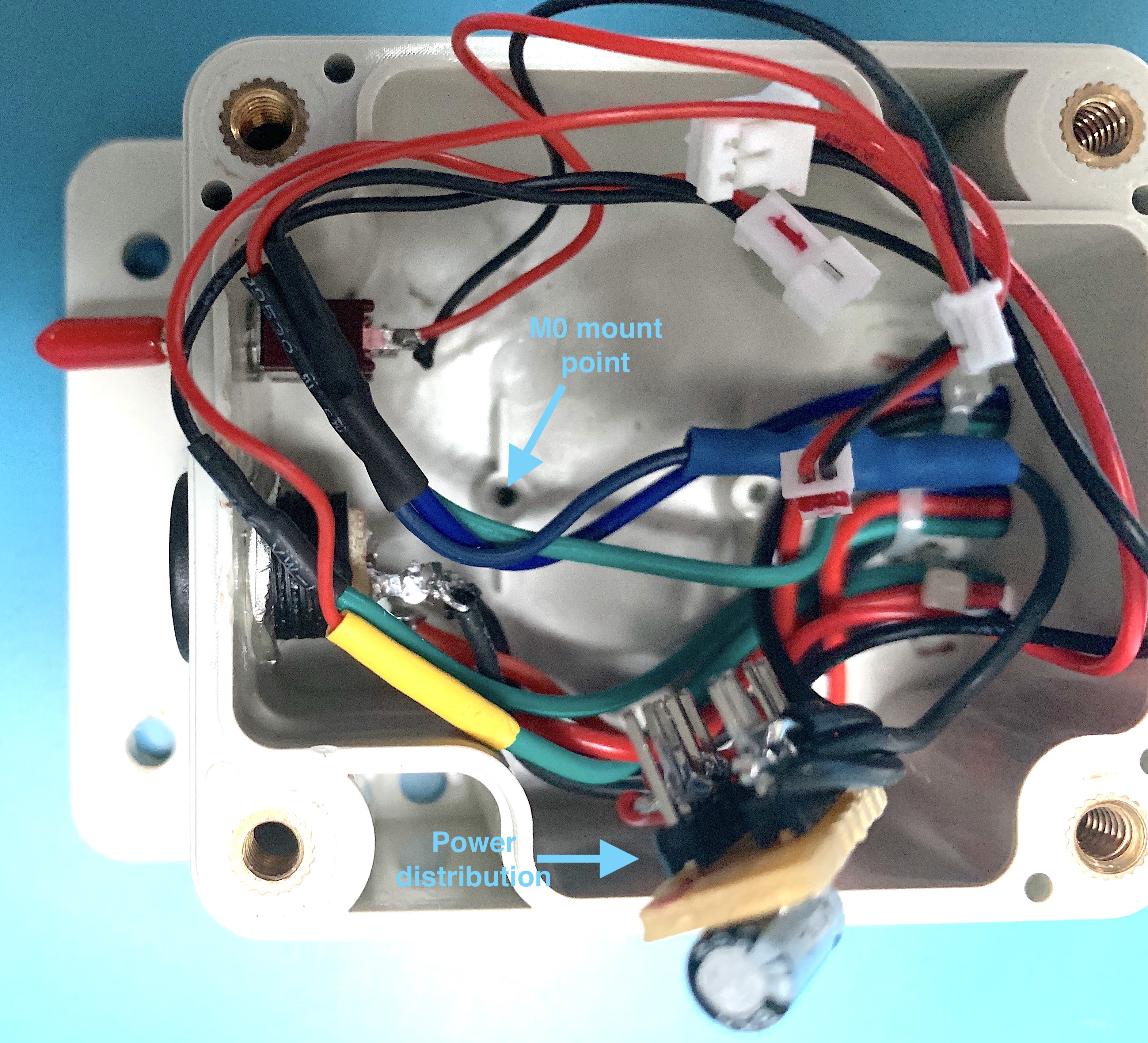
Enclosure, without the Trinket M0
Rather than leave the power distribution board exposed risking a short circuit, I slipped a large piece of shrink wrap tubing over it. But I didn't heat shrink it. With the Trinket M0 installed, the enclosure looks like this.
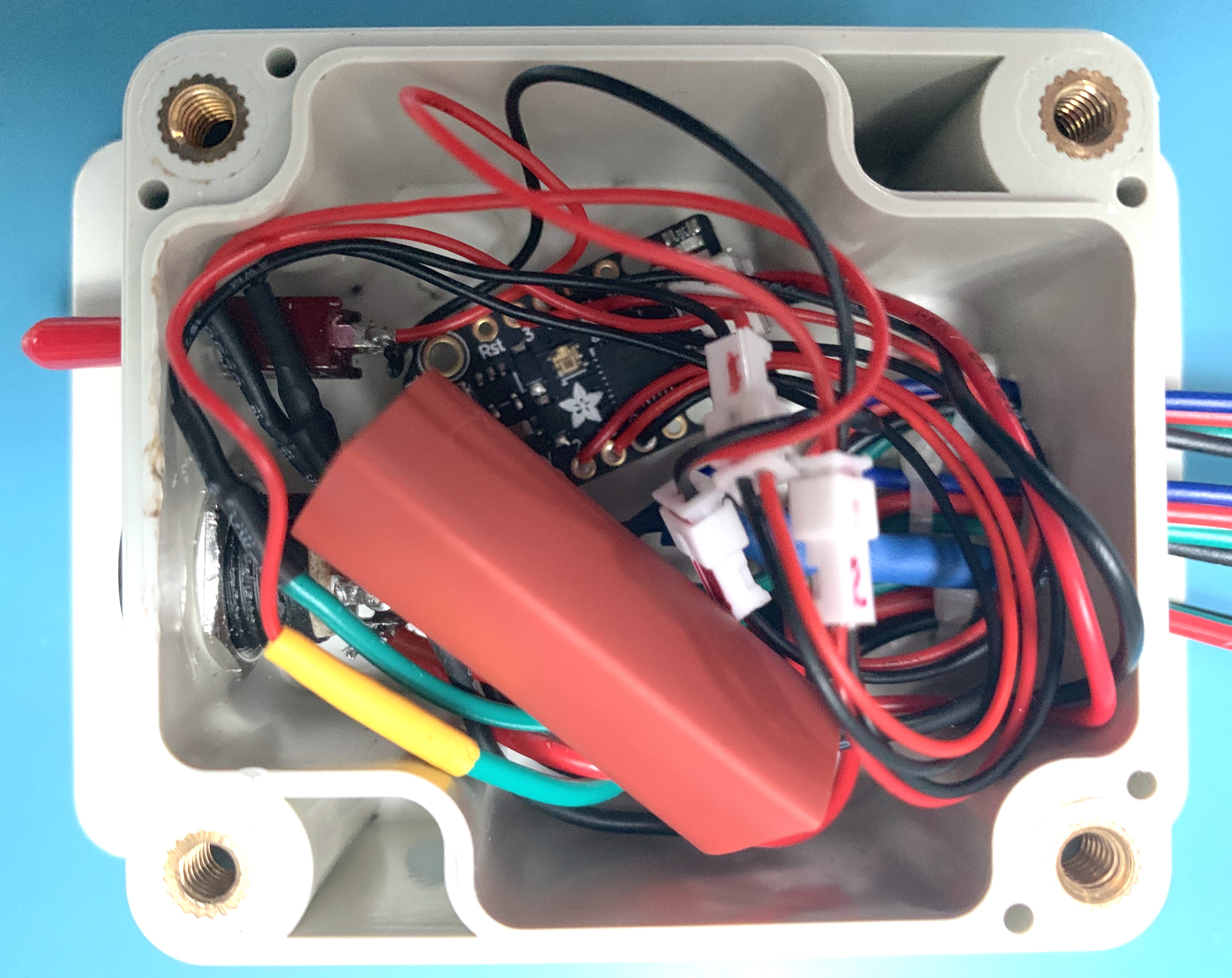
Enclosure, without the Trinket M0
The finished electronics enclosure looks like this
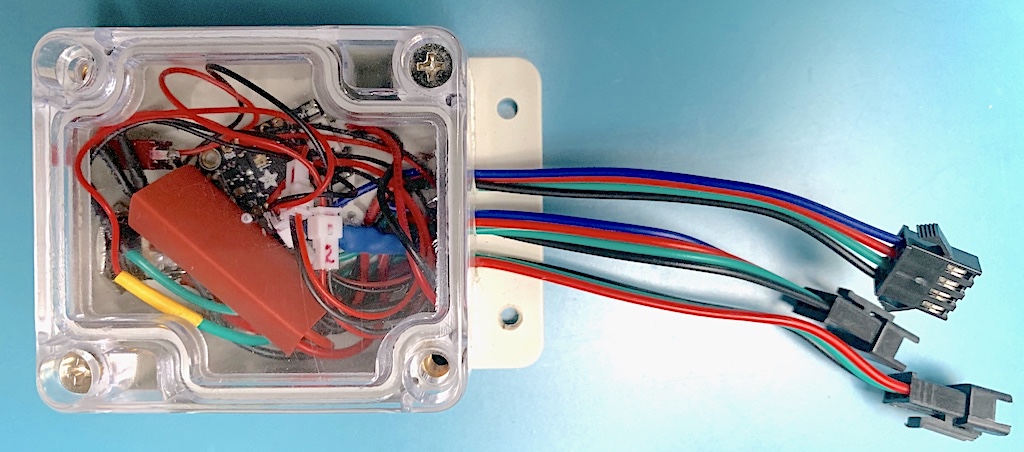
Completed electronics enclosure
The completed enclosure was installed at the bottom of the stairs in a somewhat non-intrusive manner. The enclosure is screwed to the molding with 2 wood screws.
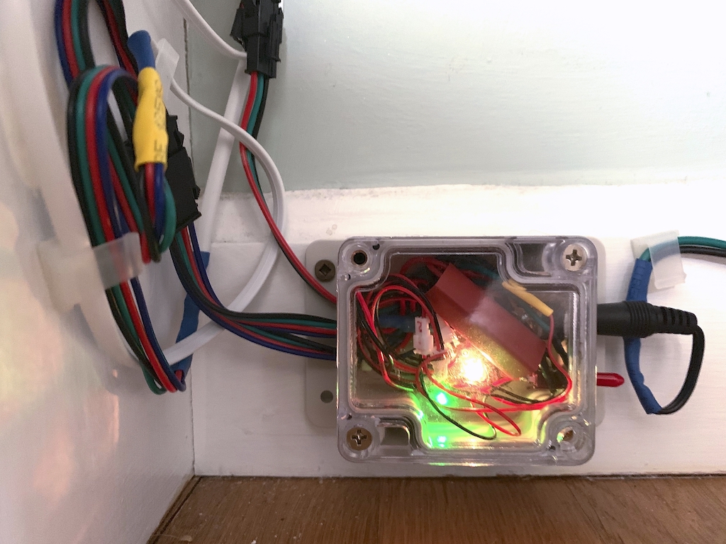
Installed enclosure
Installing the LED strip
The "dry fit" technique described above was also used with the LED strip to decide where to cut it. As it turned out, I ended up with a strip containing 111 LEDs. Once the strip was cut to size, it was time to install the LED strip. Make sure you modify the line of code
const uint16_t LEDCount = 111; // # LEDs we're working withAs mentioned earlier, the step I though would be simple turned out to be a nuisance. Nothing stuck to the strip so I ended up purchasing some cable clips that the description suggested would fit. They didn't. So rather than search again and wait for delivery, I simply modified the clips so that I could use them.
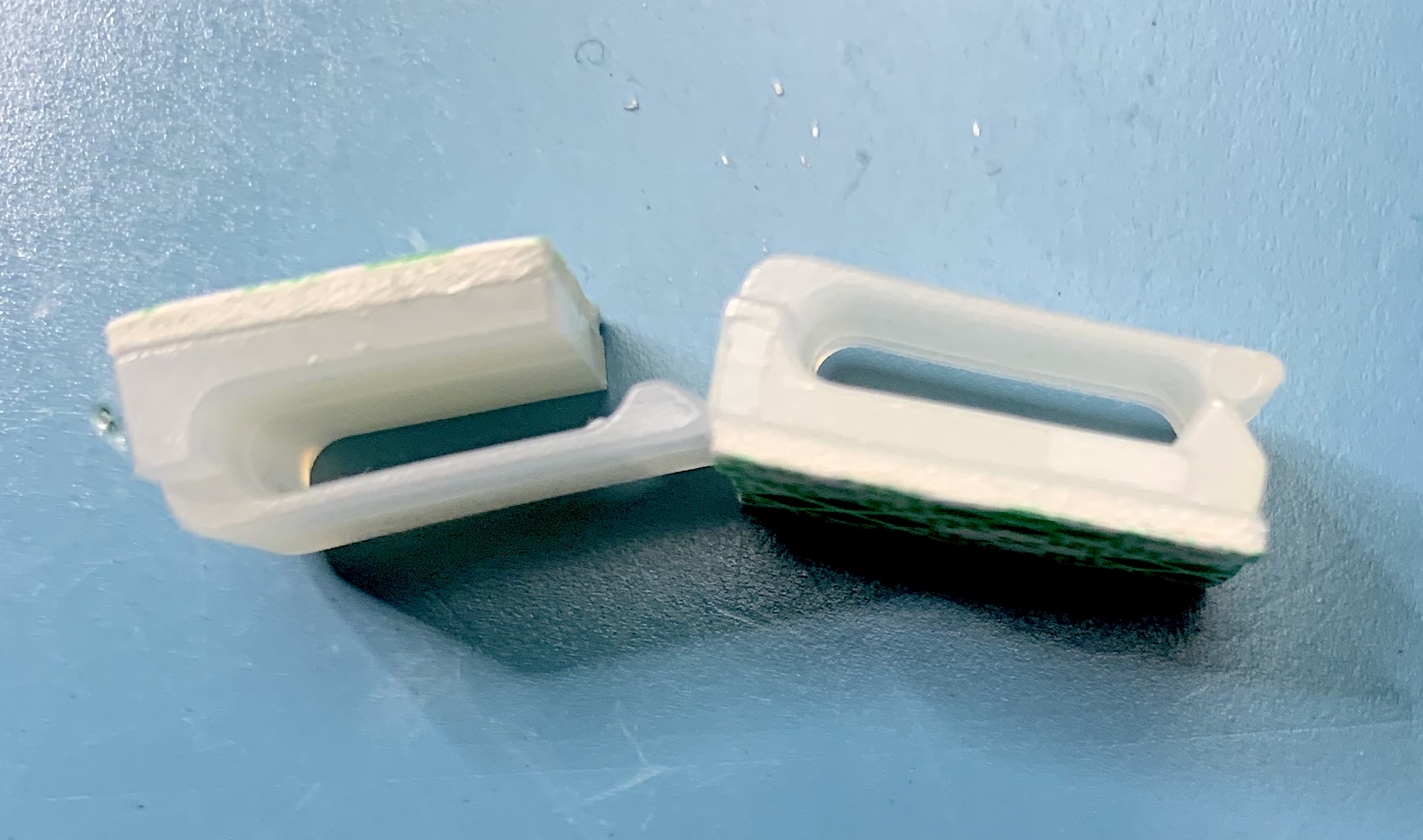
Left: modified clip, Right: clip as sold
Mike at Adafruit support let me know that E6000 adhesive will bond very well to the silicone casing. (Thanks Adafruit support!) For some reason, I never stumbled across this product. E6000 adhesive is readily available from crafting stores like Michaels and AC Moore, and from Amazon (one seller)
I was able to cut off a portion of the clip using an x-acto knife. The blade used was a #18 blade on a #5 heavy duty plastic handle. I used a spring clothes pin to hold the clip so my fingers were nowhere near the blade. Surprisingly, a straight downward cut offer only modest resistance. It took maybe 5 minutes or so to modify 20 of the clips.
The modified clips were then installed between the LEDs (over the section connectors), about every fourth one. That is, four LEDS, then a clip. The clips are stuck to the molding using the double sided tape provided on the cable clips.
Our stairs take a 90° left turn near the bottom. As a result, the LEDs strip must be carefully bent to negotiate the corners involved. I added a piece double sided mounting tape larger than the original adhesive to on the back of the cable clips near those corners.
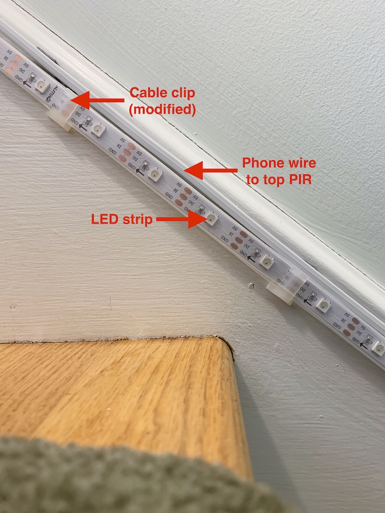
Installed LED strip and cable to top PIR
Wrap up
That's about it. Here are some video clips of the of the system in operation.
Color Fill animation, top to bottom
Since the bottom PIR was never tripped, the lights return to the top. If the bottom PIR had tripped, the lights would have turned off from top to bottom — chasing you down the stairs.
Color Swirl animation
Twinkle animation